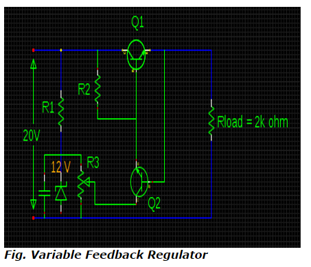
Compute the values of VOUT & P1 in a variable feedback regulator circuit with Vin = 20V, Vz = 12V & RL = 2K if the transistor is of silicon and the wiper of R3 is adjusted in half-way configuration.
a. 16.8 V & 137.76 mW
b. 10.7 V & 80.09 mW
c. 6.7 V & 43.89 mW
d. 4.7 V & 35.79 mW
Correct Answer: c. 6.7 V & 43.89 mW
Explanation From the configuration of feedback regulator circuit,
V
OUT = Voltage at wiper + V
BE2Voltage at wiper must be equal to half the Zener voltage since wiper is adjusted in half way configuration.
V
OUT = (12 / 2) + 0.7
= 6.7 V
P1 = V
CE1 x I
E1 But, V
CE1 = V
in - V
out = 20 – 6.7
= 13.3 V
I
E1 = I
L = V
out / R
L = 6.7 /2k = 3.3 mA
Therefore, P1 = 13.3 x 3.3 = 43.89 mW


